D.I.Y high clearance bumper…
I don’t often post about or share any updates about my daily driver, a 2003 Toyota 4Runner. I just doesn’t seem to special or note-worthy since I see it as just a commuter, but just like any vehicle I’ve ever owned, I just couldn’t leave it completely stock. As a matter of fact, this post is actually about a project that I completed in December of 2021…
When I bought this 4Runner, it wasn’t exactly in the best shape, and had a damaged front bumper, but I’ve always liked how these looked with a high clearance front bumper. With the bumper being already clapped, it was the only reason I needed to get a steel bumper. The downside is that these usually come at a huge cost and typically require some supporting modifications, like an upgraded suspension system to handle the additional weight. I did already change out was the original factory suspension in favour for an Eibach Stage 1 lift kit, so that was covered. Next was just to figure out which bumper to go with.
There were plenty of options to choose from and after doing the rounds on the internet, I had landed on the style of one that I liked and at a reasonable price point. However, it looked quite simple in terms of the design and if you know me, you would know that my naïve self would believe that I could build one completely from scratch…
So that’s exactly what I did.
Rinsing away the winter grime to begin the project.
I started recording with my camera with zero direction of what the video would end out to be. I had the intentions of making a full length video but never got around to it. I decided to instead repurposed the videos and made some GIFs from them to be used in this blog post. I hope you enjoy and that the GIFs contribute to an interesting reading experience.
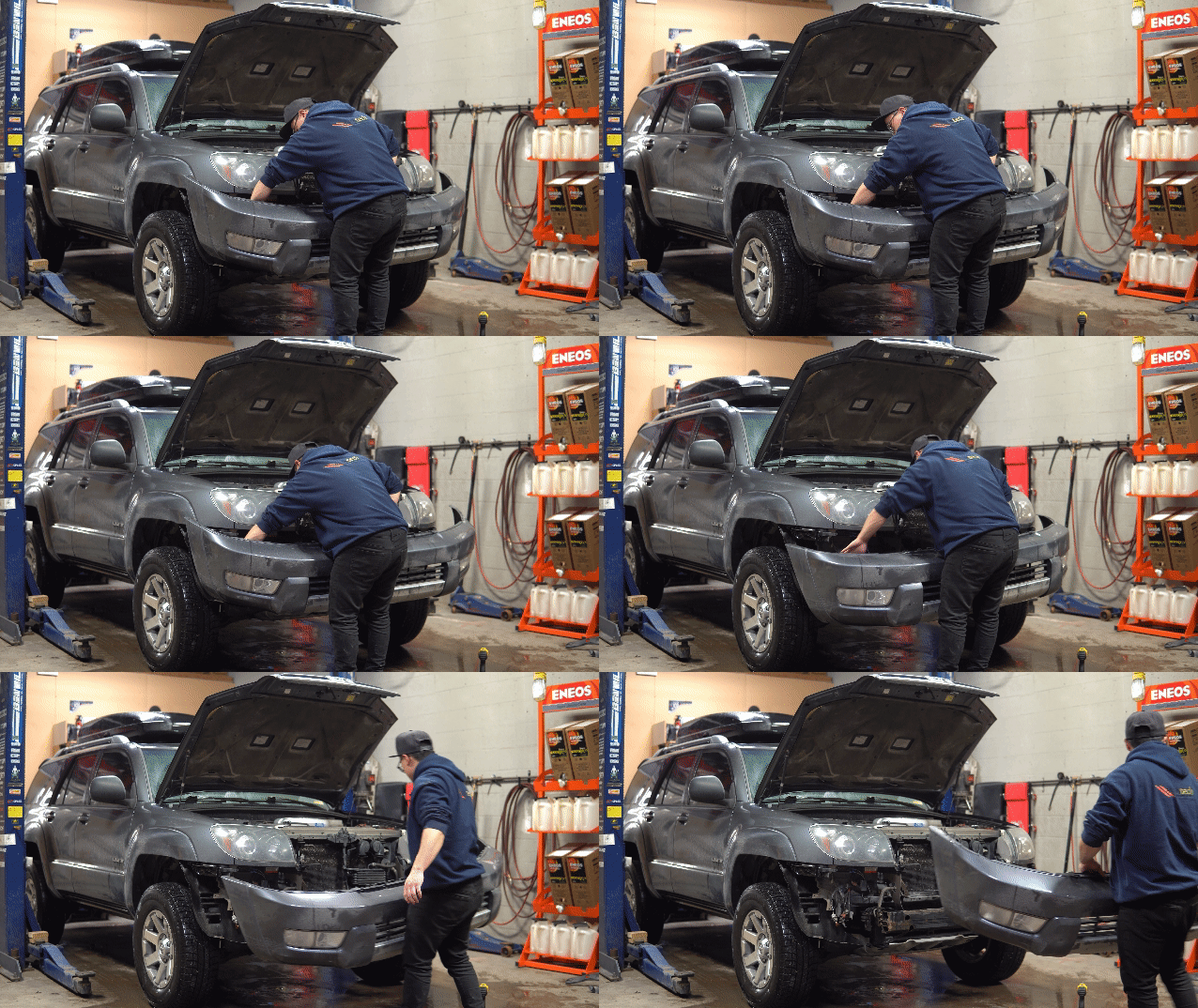
Secondly, we remove the front bumper, of course.
Maybe hard to tell here in GIF quality, but the front bumper had been poorly repainted so there were large bits of paint flaking off along with cracks in the cover around the driver side headlight.
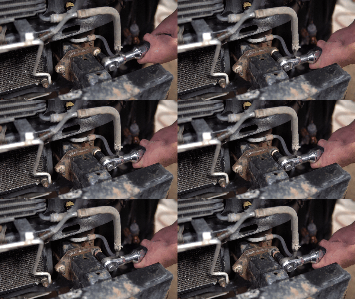
Removing the front crash support beam. This is where the new steel bumper would mount meaning the crash beam would not be reused.
I only took photos in portrait during the prototyping period as I was shooting for Instagram at the time. At first I used cardboard to get a general idea and measurements of each plate I needed. I didn’t get that process on camera, but I did for the second prototype which I recreated with foamboard and hot glue, which is seen here. Since cardboard was free and plentiful, I made multiple cutouts and variations to pieces to figure out the general shape and construction.
After I was happy with a draft, I purchased some foamboard to recreate it again. Since foamboard has greater rigidity over cardboard and I was able to get more precise with the measurements for when I was going to draw the final part in CAD.
How would you rate my “dime-stacks” with the hot glue gun?
Here is the CAD drawing of my exact bumper after the measurements were made and translated from foamboard to the computer. If you’re familiar with Toyota truck modifications then I’m sure you can already see which design I loosely based mine off of.
In being able to design my own bumper, I was able to customize it to my liking as well as include the cutouts for some Baja Design S2 flush mount lights which I wanted fitted into the bumper. The other cutout in the middle is for if I ever decide to run a mounted hitch in the bumper, so holes for a fairlead were included. Other holes were simply design choices I made.
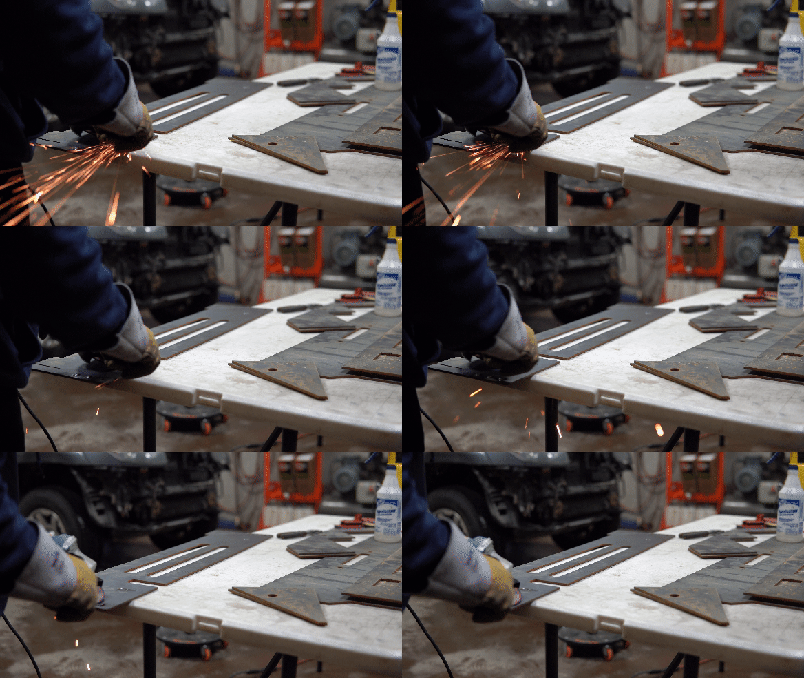
I created each piece of the bumper in CAD software then had it sent off to a local waterjet cutting shop to get the steel cut in the desired shapes. Once I picked up all of the pieces, it was then like putting together lego - kinda. Here I am grinding away a bit of the surface of the steel in areas that I planned on welding.
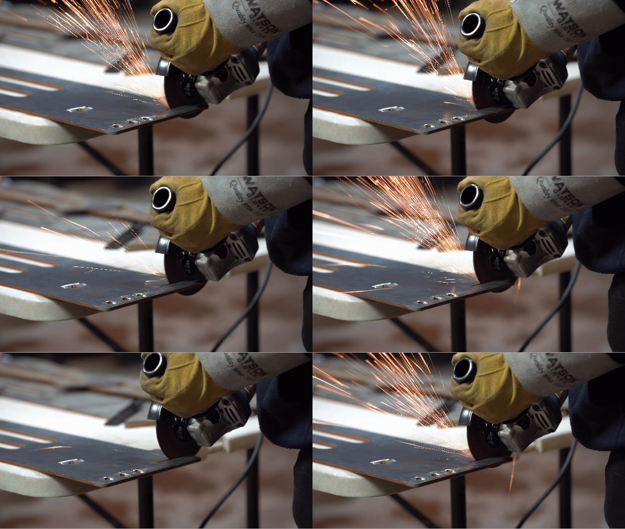
Like any time you do something for the first time, there tends to be some margin of error. Here I am enlarging a slot where I had the tolerance set in my CAD drawing to be absolutely perfect, but that doesn’t exactly reflect real life. I didn’t need to take off much, but this taught me to mind tolerances a bit more closely when I’m designing with CAD.
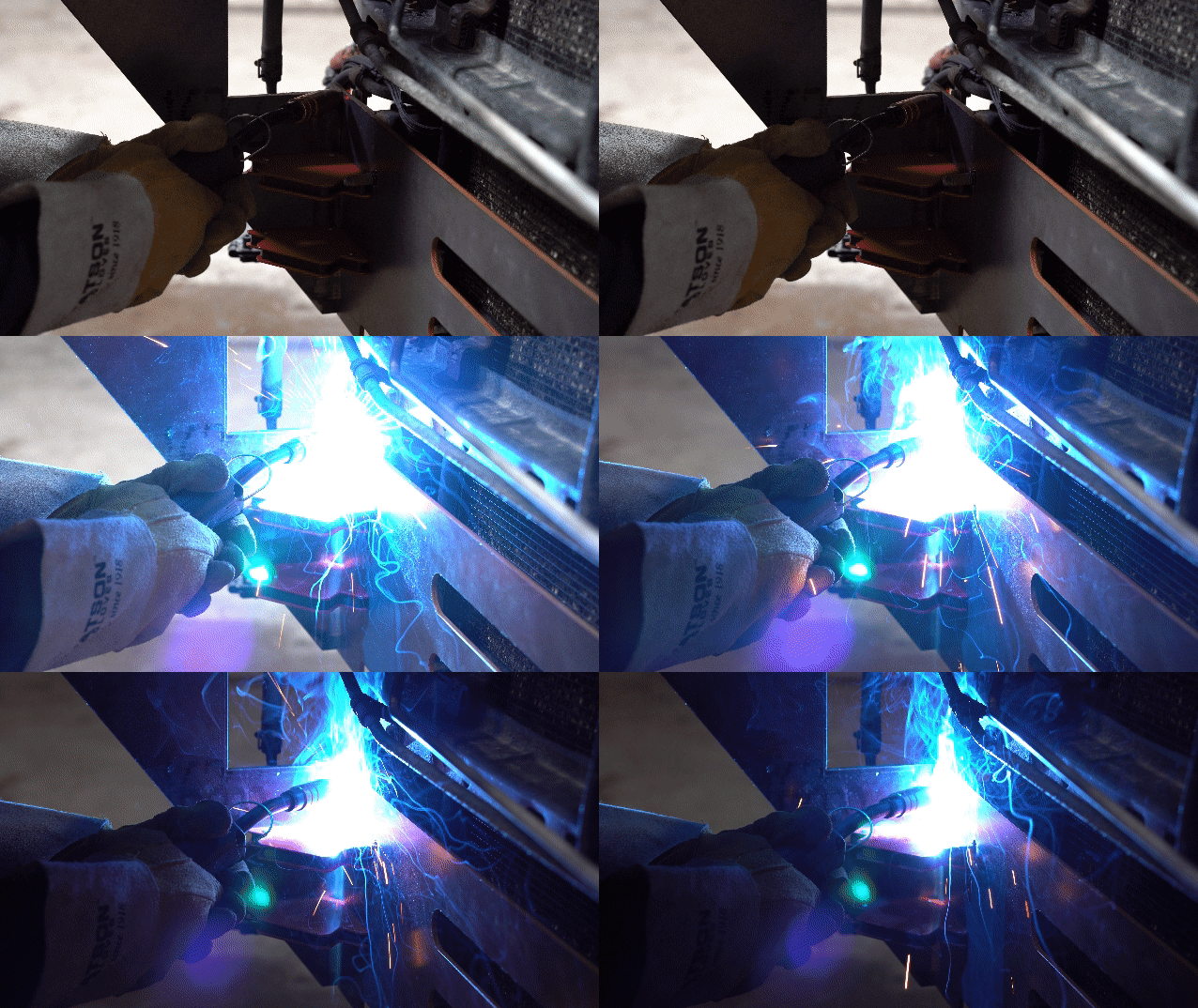
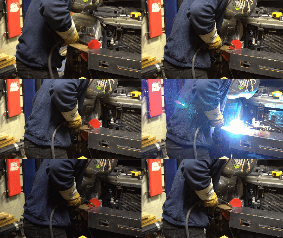
After fitting the first pieces of the bumper, I began to start tacking it together. This was also my second time ever holding a welding gun. The first time was welding the JDM front end on my Integra, but those were only tacks. Welding was by far the most challenging part of this project, but also the most fun and rewarding.
I am no means a welder by any stretch and do not claim to be one. Do not rate my welds.
I think welding looks so cool on camera. You typically don’t see this process cause you’re either behind a welding mask, or you do get to see this with your own eyes once but then you don’t get to see ever again.
Main structure of the bumper taking shape after a few tacks.
Bolting up the main section to continue on with the other pieces. I checked often to make sure the panels lined up nicely and were as straight and flush as I could get them.
Shoutout to The Cut Shop in Calgary. I’ve gone to them for smaller projects before and they’ve always provided friendly service and quick turn-around times. I found the pricing to be great as well. They of course were a part of this project in cutting and supplying the material.
Here I’m mocking up this longer section which I dubbed the “wing plate”.
Another over sight was the angle of the front fender and that I did not properly account for this with the steel bumper. You can see here that the fender has a slight angle upwards towards the wheel well and causes a sizeable gap between. I did realize this during the foamboard phase, but it was not as exaggerated since there is flex in foamboard while there is not much in steel.
Since all of the pieces were already cut, there wasn’t much I could do at this point. I pushed the wing up as much as I could but there was only so much I could make up as to not create too much of a gap with the adjacent pieces.
Adding tacks along the top of the passenger side wing plate.
I don’t actually know what I’m doing.
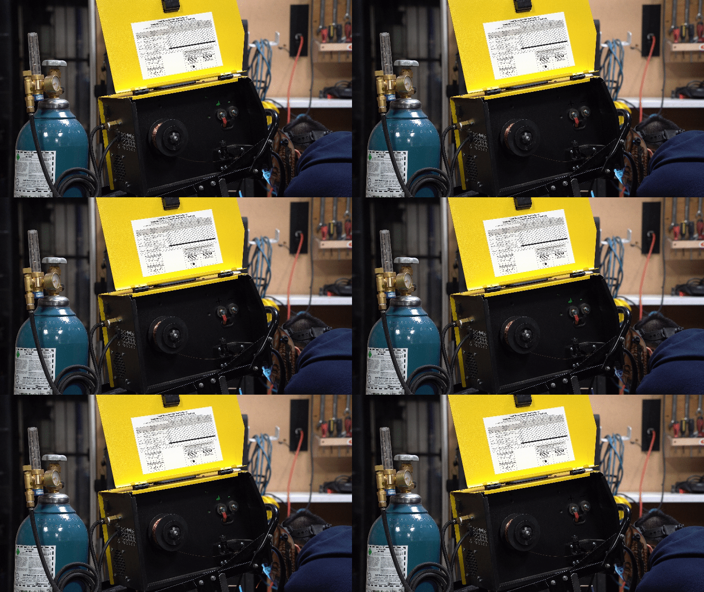
Shielding gas is a must when welding. It will control the splatter around the welding area. There’s probably more to it but I’m not a welder so I don’t know all of the details to it. I wouldn’t have even wanted to see my welds without it.
At this point, I think it was getting late so I was just trying to get all of the welding done. I didn’t record much past this point as the process was pretty much the same here on out. One part I missed out on recording was the grinding process. Once I had the entire bumper welded up, I used a flap disc to clean up the welds and to round off the edges to give it a better finished look.
This part also revealed any pinholes or burn through that I went back to fill and grind down smooth again.
I came back the next morning with less hair and got ready to get the bumper painted. This was my ingenious approach to painting the bumper. Complete it weighs probably around 80 lbs, so it’s not exactly easy to maneuver, but with it strapped to the hoist I could paint it all in one go.
I prepped it with wax and grease remover before laying down self-etching primer. I chose to use rubberized undercoat in black to finish the bumper in.
The downside to having it strapped the way I did was that I was painting it upside down. Typically you would want to paint a part in the same orientation as it would be when installed on the car as this would give the best looking finish. Since I’m using undercoat instead of paint, this was not a huge concern as it dries flat in appearance.
A battle I was having here instead was that the rubberized undercoat sprays out heavy and can easily run because of that. You could aim further back to help reduce the running, but the texture would not be as nice. Aim to closely and you get good texture but you need to move very quickly move or else you’re bound to get runs. There is a fine balance of painting skill and patience to achieving the most desirable finish with an even texture and coverage without runs.
I did not find balance.
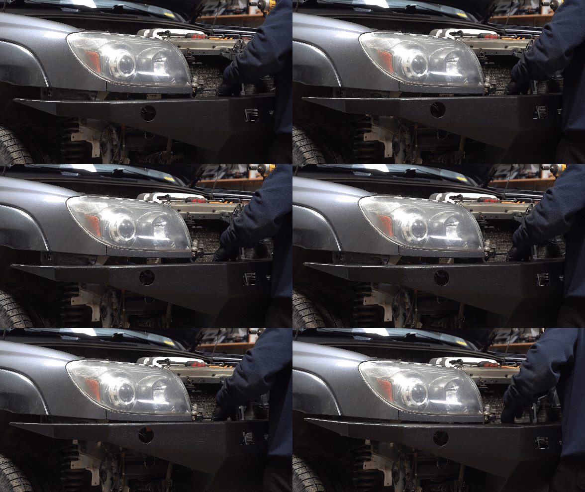
Mounting the bumper is easiest when using proper deadlift and pelvic thrust technique.
The OEM signal light sits in the front bumper, so I needed replacement signals. I got these generic 2.5” trailer signal lights. I’ve since replaced these with clear lens with brighter amber LEDs.
These LEDs did require resistors to adjust the resistance of the circuit to prevent any hyper flashing.
And that’s a wrap! This turned out to be a fun project and while there were many things that did not go as planned, I am still pleased with the end result.
I’m sure a question many people (including myself) would ask is, “was it worth it?” First off, I didn’t exactly save much money in getting the material cut locally versus purchasing a DIY weld kit from a company - really only saved on shipping costs. Given the time spent to prototype and design, I would say I lost here due to the amount in labour hours.
The positives here are that I can say that I’ve done this from scratch which gives me the confidence to take on more types of projects like this. I’m already thinking of designing another bumper - this time being a hybrid bumper with tubes. CAD is something I’ve been having a lot of fun with lately and this was one of the gateways to that. It’s a very simple design overall and while I can’t exactly say that this design is unique or original in any way - knowing that I was able to envision something in my head, plan out the process, do the assembly and then to come out the end with the physical thing is pretty awesome.
Modding something like this truck is great cause I don’t exactly care for it to look or be perfect - unlike my car. It allows for greater freedom when designing something that doesn’t need to be absolutely aesthetically pleasing, just mainly functional. I think that’s also just due to the vibe and style of these trucks. Majority of the people who own these are modding them to be practical, rather than for show, but that in a way adds to the overall look and becomes an aesthetic…
Here is a recent photo of the 4Runner - albeit rather dirty… it’s been about 2 years and while I still love the look of it, I’ve been thinking about changing up the bumper. Although, I think the itch comes more from the challenge of wanting to design something new, rather than going through the process of assembly...
What do you think I should make next? Let me know in the comments.


